Picture: wire rope transmission in Schaffhausen, Switzerland, 1896. Source: Stadtarchiv Schaffhausen.
You don’t need electricity to send or receive power quickly. In the second half of the nineteenth century, we commonly used fast-moving ropes. These wire rope transmissions were more efficient than electricity for distances up to 5 kilometres. Even today, a nineteenth-century rope drive would be more efficient than electricity over relatively short distances. If we used modern materials for making ropes and pulleys, we could further improve this forgotten method.
The rope drive is the culmination of a long history of mechanical power transmission. In the 1500s, mining engineers designed "Stangenkunsten": a method to transmit power from distant water wheels to machinery at the mineshaft, using reciprocating wooden rods. This early predecessor of electricity was improved in the 1860s oil industry’s "Jerker line systems", which used steel cables instead of wooden rods.
The need for long-distance power transmission appeared first in the mining industry because mines could not be relocated to a nearby water power source. In the nineteenth century, the need for power transmission spread to other industries because the demand for power had grown considerably with the arrival of the Industrial Revolution, and most available water power resources had already been put to use — especially in Europe. A new form of power transmission was needed to make previously inaccessible sources of water power available. For instance, many powerful water sources in mountainous areas were idle because these sites were unsuitable for building factories. The development of steam engines also called for power distribution and transmission, especially in Great Britain and in the US, because smaller engines were uneconomical to operate.
The pioneering power-transmission technology developed by the mining industry was not suited for most of these new demands. A Stangenkunst or jerker line system transmitted power using a reciprocating motion, while most industries required circular motion to drive machinery. Although these systems could be adapted to convert reciprocating motion into circular motion, this was possible only at low speeds and the expense of considerable energy loss [1]. Apart from this, the power that could be transmitted by a mere dead pull was limited. Enormous wooden rods or steel cables would have been needed to transmit the amount of power that could be harvested from mountain streams and waterfalls [2].
The Millwork
Around 1850, the only available technology for the transmission of fast, circular motion was the so-called "millwork". This combination of shafts, gears, belts and pulleys was aimed at the distribution (rather than long-distance transmission) of mechanical energy. It transferred power from a prime mover (a water turbine or a steam engine) to individual machines.
A factory interior in Schaffhausen, Germany.
While the nineteenth-century millwork was considerably more efficient than the large wooden gears and shafts in the pre-industrial wind- and watermills from which it evolved, it was not suited for longer distances. One engineer calculated that 75% of the power transmitted by a lineshaft would be absorbed by friction of the bearings at a distance of between 95 to 600 m [3]. Moreover, millwork required protection from the weather and so could not be operated outdoors.
A factory interior in Schaffhausen, Germany.
Even for short distances, nineteenth century millwork was rather inefficient. A major investigation in the early 1880s covering 55 industrial establishments, chiefly textile mills, revealed that the combined power losses in engines and millwork were on average 25%. For machine shops, the energy loss was on average 40 to 50% [4]. Line shafts were also hungry for space, costly to install, troublesome to maintain and adjust, hazardous in use, and inflexible in arrangement.
Wire Rope Power Transmission
Late nineteenth-century industry was in need of a more efficient and versatile method of power transmission for both short and long distances. Several alternatives were in the running: power could be transmitted by electricity, compressed air, hydraulics, steam, millwork, or ropes. While electricity eventually won the battle, a few others deserve more attention [5].
Rope transmission, the subject of this article, stands apart from all other power transmission technologies because it doesn’t involve any conversion of energy. An endless rope drive transmits mechanical energy directly from a power source to machinery. As we will see, this makes rope transmission more efficient than any other alternative up to a distance of a few kilometres.
Contrary to electricity and compressed air, the transmission of power by rope was not a radical departure from traditional methods. Conceptually, wire rope transmission simply extended the range of millwork by improving its efficiency and flexibility, and by making it weather-proof. Rope transmission started in the 1840s as an element of millwork, using fast-spinning fibrous ropes as an alternative to belts transmitting power from the prime mover to the line shafts [6]. When fibrous ropes were replaced by metallic ropes (or "wire ropes"), a long-distance power transmission was born.
Wire Rope
Interestingly, the wire rope itself can be traced back to the same region that invented the Stangenkunst in the 1500s: the Upper Harz mining region in Germany. In the 1830s, mining engineer Wilhelm Albert twisted together several strands of metal wire around a hempen core, resulting in a superior hoisting cable for use in vertical shafts. Compared to a fibrous rope, a wire rope is much stronger, despite being the same weight and diameter. Unlike fibrous rope, it keeps its strength when it is wet, and its length remains constant under all weather conditions.
Metallic ropes were used throughout the global mining industry during the 1800s, replacing metal chains and fibrous cables for hoisting up ores and transporting miners up and down shafts. The wire rope also led to important uses outside the industry. It enabled the invention of the suspension bridge and came in handy as a means to carry other static loads such as smokestacks and masts. But its main applications involved moving passengers and goods, both vertically and horizontally. The wire rope gave birth to the elevator and made cranes and hoisting machines much more powerful. It introduced new transportation options on land (as in cable trains), on water (as in rope-powered canal boats), and in the air (as in aerial ropeways).
How did it Work?
Few know that wire rope was also used to transmit energy across land. A wire rope power transmission, or "telodynamic transmission" as it was initially called, was basically an aerial ropeway running without vehicles, at higher speeds. Both aerial ropeways and wire rope drives were sold by the same manufacturers. Wire rope transmissions used thin wire ropes (up to 2.5 cm in diameter) and large, cast-iron pulleys (up to 5 m in diameter), mounted on wooden, iron or masonry towers placed at maximum intervals of 90 to 150 m. The bottom of the pulley grooves was made of strips of leather to limit the wear of the rope.
Detail of the wire rope transmission in Neuthal, the only remaining wire rope transmission line in Europe. Photo credit:Peter Christener.
The fundamentals of the method were concisely described by Albert Stahl in his 1889 treatise Transmission of Power by Wire Ropes:
"The construction of the apparatus is very simple. A tolerably large iron wheel, having a V-shaped groove in its rim, is connected with the motor, and driven with a perimetral velocity of usually from 50 to 100 feet [per second]. Round this wheel is passed a thin wire rope, which is led away to almost any reasonable distance (the limit being measurable by miles), where it passes over a similar wheel, and then returns as an endless band to the wheel whence it started."
For longer wire rope transmissions, two configurations were possible. Either one, long continuous rope was used, supported at intervals by carrying sheaves, similar to those of an aerial ropeway. Usually, though, a wire rope power transmission used shorter ropes that extended between stations, instead of running the whole length of the transmission. Each tower then served as the driver for another by means of a double pulley arrangement, or a double grooved wheel.
When using carrying sheaves to bridge larger spans, it was often sufficient to support only the slack side of the rope. The illustration above shows the different arrangements used for wire rope transmissions. When the rope drive had to change direction, or when the power had to be distributed to a number of consumers, this could be done by using either horizontal sheaves, or more frequently, bevel gearing/wheels.
Diffusion of the Technology
The use of wire rope for power transmission over long distances was invented by the Hirn brothers in 1850, while they were setting up a weaving factory in an abandoned textile works near Logelbach, Switzerland. The buildings were scattered over considerable distances and setting up multiple steam engines would have been too expensive. Following some initial problems (finding a suited material as a seating for the ropes proved to be one of the biggest) the Hirn Brothers set up power transmission lines between the buildings. The longest line reached 235 m, transmitting 50 horse power (hp).
After the initial success of the Hirn installation, the technology spread rapidly throughout the Alps, and beyond. W.C. Unwin gives a detailed overview of the initial diffusion of telodynamic transmissions in his 1894 book On the Development and Transmission of Power from Central Stations:
"Soon after the erection of the transmissions at Logelbach M. Henri Schlumberger transmitted the power of a turbine 86 yards to work agricultural machinery. In 1857, at Copenhagen, Captain Jagd transmitted 45 hp to saw-mills at a distance of more than 1,000 yards. In 1858, at Cornimont, in the Vosges, 50 hp was transmitted 1,251 yards. In 1859, at Oberursel, 100 hp was transmitted 1,076 yards; and at Emmendingen 60 hp was transmitted 1,372 yards. In 1862 Hirn stated that about 400 applications of the telodynamic system had been constructed by Messrs. Stein & Co., of Mulhouse, carrying an aggregate of 4,200 hp over distances amounting altogether to 80,000 yards."
These installations had an average capacity of about 10 hp and a transmission distance of about 180 m. By 1869, two years after Hirn’s invention received an award at the Universal Exposition in Paris, about 2000 permanent installations had been constructed on the European Continent. Most were relatively small ropeways, but some were fairly large. The Hirn system was adopted in three of the earliest central power stations in Europe: Schaffhausen (1864) and Fribourg (1870) in Switzerland, and Bellegarde (1872) in France. These installations transmitted between 560 and 3150 hp by wire ropes, over distances up to 966 m.
The Schaffhausen Transmission
The Schaffhausen transmission is regarded as the most complex wire rope transmission ever built, using 1027 m of ropes, aggregating more than 600 hp. After a period of trade depression there was a revival of industry at Schaffhausen. The required energy was found in the immense volume of water passing down the rapids of the Rhine in front of the town. Since the steep rocky banks forbade the erection of any factories in the immediate neighbourhood, the power was transferred diagonally across the stream to the town, about a mile lower down, and there distributed, with certain rocks in the water being used to set up the intermediate stations.
The Schaffhausen wire rope transmission in 1896. Source: Stadtarchiv Schaffhausen.
It is interesting to republish Unwin’s full description of the Schaffhausen installation, because "it is essential to learn how far wire-rope transmission can be adapted to complex situations where many consumers require power":
"A weir was constructed during favourable seasons in 1864-66, across the rocky bed of the river, which is about 500 feet wide. By placing the turbine-house in the river-bed near the weir and constructing a tunnel tailrace 620 feet in length, a fall was obtained which varies from 15.6 to 13.7 feet. The turbine house contains three turbines with vertical shafts of 200, 260, and 300 hp, or 760 hp altogether. They gear with a common horizontal shaft by means of bevil gears. About 150 hp is transmitted from one of the turbines to a factory on the hill above the turbine-house, by a steel shaft 550 feet in length. From the same shaft also about 22 hp is transmitted, by a small cable passing down the left bank of the river and then crossing it, to a pulp factory on the right bank."
"This leaves a maximum of about 570 hp to be dealt with by the main cable transmission, which crosses the river directly from the turbine-house, and then passes along the right bank to the factories. The turbines are connected to two principal rope pulleys of 14.75 feet in diameter. From these pulleys two cables cross the river in a single span of 385 feet to a pulley station in the river at the left bank, where the direction of the transmission is changed by bevil gearing, and thence the transmission passes up the left bank of the river. The gross power in the horizontal driving shaft in the turbine-house is about 350 hp or, allowing for friction, say 500 effective hp to be transmitted to the factories, or 250 hp for each rope. Either rope is capable of transmitting at any rate a large fraction of the whole power temporarily, if the other rope is broken. The power is delivered by the ropes at the change station on the left bank. At that station about 22 hp is taken off by prolonging the second shaft of the bevil gearing and a subsidiary rope transmission."
"The remaining 478 hp is transmitted along the left bank to the first intermediate pulley station at a distance of 370 feet by a pair of cables. Thence to the second intermediate station, distant 345 feet, by another pair of cables. At 455 feet further is a second change station, at which the direction is again changed by gearing. Thence the ropes pass to two other intermediate stations. From the second intermediate station an underground shaft carries about 27 hp to ten small workshops, and from the second change station, and the third and fourth intermediate stations, cables are carried back across the river to factories on the right bank. From the first shaft on the second change station about 110 hp are distributed, partial by a special rope gear, partly by vertical and underground shafting, to four factories, one of which is the large Mosersche Gebaude; and from the second shaft of this station a steel shaft transmits 200 hp to Scholler’s wool factory."
The Schaffhausen installation was a greatly successful undertaking. The number of renters of power grew from 13 in 1867 to 23 in 1887, while the average total horse power supplied grew from 121 to 641. The total income from rental of power rose tenfold.
Other Examples
The wire rope transmission at Fribourg, where the ravine is not suitable for factories, was no less impressive. Here, a wire rope transmitted 300 hp to an industrial site 90 m above the river. Power was distributed via wire ropes to a sawmill, a foundry, a chemical factory, a rope tramway for carrying timber, and a railway carriage works. The total distance of the transmission amounted to more than 1500 m. Part of the line passed through a specially designed tunnel.
At Bellegarde, which lies about 25 km from Geneva, 3150 hp was transmitted in different directions via wire ropes from the river Rhône to the plain above, where it was used to operate a phosphate works, a wood pulp factory, a paper mill, a copper refinery and a pumping station. The transmission lines reached a total length of more than 900 m.
Most wire rope transmissions were built in France, Switzerland and Germany, but the technology was used all over the world. Following a serious explosion, an installation was put up at a gunpowder factory at Ochta near St. Petersburg, Russia, in 1867. A total of 274 hp was transmitted by more than 3000 m of wire rope to 34 widely scattered workshops and laboratories. The wire rope transmission was adopted to ensure that the buildings should be at a safe distance from each other were another explosion to occur.
At Gokak, India, a large telodynamic transmission was set to work in 1887. A total of 750 hp was transmitted to a large cotton mill via three wire ropes (illustration below).
Numerous wire rope installations were built in the United States — a total of 400 telodynamic systems were reported in 1874. Most prominent were those at Lockport (New York), Lawrence (Kansas), and near Great Falls (Montana) on the upper Missouri River [7]. However, none of them approached the size of the Schaffhausen plant in Switzerland. The technology seems not to have attained the popularity and importance that it did in the regions of its principal continental use, writes Louis Hunter, who adds that "this was no doubt owing to the greater abundance of water powers in the US in a wide range of capacities, and to the abundance of coal and the rapidly increasing acceptance of steam power from the 1850s."
Efficiency
It may seem that wire rope power transmissions running over hundreds and sometimes thousands of metres, could not be very efficient. However, a wire rope transmission was considerably more efficient (and cheaper) than electricity up to distances of about 5 km (3 miles). As with jerker line systems, the efficiency advantage was due to the fact that in a telodynamic transmission mechanical energy can be transmitted without conversion losses. This was emphasised by W.C. Unwin in 1894:
"The telodynamic system has the peculiar advantage that it transmits the mechanical energy developed by the prime mover directly, without any intermediate transformation. In electrical distribution a double transformation is necessary: a transformation into electrical energy by a dynamo, and retransformation back into mechanical energy by an electric motor. This double transformation involves waste of power and increase of capital expended."
On the other hand, a wire rope transmission introduces friction losses. The principal source of waste in rope transmission is the friction in the journals of the wheel shafts. The friction losses become larger as the distance increases, because more pulley stations have to be introduced, while the conversion losses of electric transmission are independent of distance. (There were transportation losses for electricity, too, but these were comparatively small). Beyond a certain distance, a wire rope transmission loses its advantage over electricity.
Pulley wheel of the wire rope transmission in Neuthal, Switzerland. Picture credit.
The efficiency of telodynamic transmission was carefully examined by Ziegler, one of the better known manufacturers. He made experiments at Oberursel, where 104 hp was transmitted over a distance of 963 m, in seven spans of about 122 m each. Ziegler’s measurements showed that total loss of work over eight stations was 13.5 hp, which comes down to an efficiency of about 87%. The loss of energy was about 1.7 hp per pulley station.
From this he calculated that the efficiency of a wire rope transmission was 97% for a single span (two pulley stations), 95% for two spans (three pulley stations), 93% for three spans (four pulley stations), and 90% for five spans (six pulley stations). For nine spans (ten pulley stations), efficiency went down to 85%.
Another investigation, published in 1886, showed that wire rope had an efficiency that was largely superior for distances up to 900 m (3,000 feet), compared to the main competing technologies (electric, hydraulic and pneumatic transmission). Telodynamic transmission retained this advantage up to a distance of about 4,600 m (15,000 feet), beyond which it was defeated by electricity. In other words, wire rope lost its advantage over electricity when more than 35 pulley stations were involved. Were a wire rope transmission to be used over a distance of 18 km (60,000 feet), efficiency would go down to 13%. [8]
Note that the results are for a full load — both electrical and wire rope transmission would have been much less efficient at partial loads. Also note that the results for wire rope transmission involve power transmission in a straight line — every angle station would introduce additional losses. With regards to cost, Hunter notes that copper wire was 1.4 times more expensive than wire rope, and all nineteenth-century authors state that wire rope transmission was cheaper in construction and use than electricity, even though the ropes had to be replaced every two to five years.
How would a Present-day Wire Rope Transmission Compare to Electricity?
The advantages of rope transmission calculated in 1860 and 1886 still hold today. The only difference would be that a comparison of a rope drive and an electrical transmission would now show much better efficiencies for electricity at distances of 10 or 20 km (30,000 or 60,000 feet). In the 1880s, electricity was still transmitted by direct current (DC), which is much less efficient at longer distances than the alternate current (AC) that we use today. With AC, the losses are about 3% over a distance of 1,000 km [9].
A wire rope power transmission leaves a water power plant, heading for a paper factory in Heilbronn, Germany. The line, 90 m long, was constructed in 1888. Photo credit.
However, this efficiency would still be lower than that of a wire rope transmission over a relatively short distance, because of the double energy conversion that is required to move mechanical energy using electricity. The combined energy losses in a modern electric motor and generator are about 15%, which makes the double energy conversion 85% efficient [10]. This is better than the 69% efficiency in the 1889 table shown above, but still inferior to the efficiency of a nineteenth century wire rope transmission up to a distance of at least 1 km (3,000 feet).
Of course, it is not fair to compare a nineteenth-century wire rope transmission with a 21st-century electric transmission. With today’s knowledge and materials, a rope transmission could be improved in two ways: by using stronger and/or lighter ropes, and by running them at higher speeds. The result would be that more power can be transmitted over longer distances with less friction loss. In 1894, Unwin noted that:
"The amount of work transmitted by a cable is proportional to the product of the effective tension (difference of the tension in the tight and slack sides) and the speed. To transmit power by manageable cables, the strongest material must be used for the cables, and they must be run at the highest practicable speed."
Substituting Velocity for Mass
This brings us to the basic physics of rope power transmission: in executing mechanical work, force can be transformed into velocity and vice versa. In a rope drive, energy can be transmitted at considerable velocity and little force, while at the receiving station it can be delivered in the generally more useful form of large force and little velocity. Increasing the speed of the transmission has a similar effect as increasing the diameter of the rope.
The Schaffhausen wire rope transmission in 1896. Source: Stadtarchiv Schaffhausen.
If a rope with a diameter of 2.5 cm (1 inch) can transmit 50 hp at a velocity of 20 feet per second (22 km/h), the same rope could transmit 250 hp at a velocity of 100 feet per second (110 km/h). Conversely, if a rope with a diameter of 2.5 cm can transmit 50 hp at a velocity of 20 feet per second, a rope of only half that diameter could deliver the same amount of power if it was running at twice the speed, and should run at a velocity of 200 feet per second (220 km/h) in order to transmit 250 hp.
Theoretically, there are no limits to power transmission by rope. "To put an extreme illustration", wrote Albert Stahl in 1889, "we may conceive of a speed at which an iron wire as fine as a human hair would be able to transmit the same amount of work as the original one-inch [rope]". Conversely, we could argue that if we could learn how to run ropes fast enough, a ship hawser could transmit the power of an entire nuclear plant [11]. While this is far from reality at this point, we do have better ropes than 120 years ago, and we can run them faster.
"The amount of power which is practically possible to transmit by a single cable is limited. It is not possible by increasing the size of the cable to transmit an indefinetely large amount of power. The cables become too heavy to be manageable, and the pulleys too large in diameter. (…). The peripheries of the driving wheels may have an anular velocity as great as convenient; the only limit, in fact, being that the speed shall not be so great as to involve any danger of destroying the wheels by centrifugal force. One hundred feet per second has been adopted as the greatest practicable speed."
Running Stronger Ropes at Higher Speeds
Today we have ropes made of artificial fibres, which have a similar tensile strength to wire ropes, but at one fifth the weight. Such ropes make it possible to place pulley towers further apart, reducing the friction loss and improving the efficiency of a rope transmission over longer distances. We could also try to run thicker ropes if they are lighter, thereby converting an efficiency advantage into a higher power capacity.
The Schaffhausen wire rope transmission in 1896. Source: Stadtarchiv Schaffhausen.
It’s also possible to build sturdier pullies, allowing us to run these ropes faster. Higher speeds would allow more power to be transmitted at the same rope diameter, or further improve efficiency (because we can transmit a similar amount of power using lighter ropes). Albert Stahl already foresaw this possibility in 1889:
"The wheels themselves are made as light as is consistent with strength, not only for the sake of reducing the friction on the journals of their shafts to a minimum, but for the equally important object of diminishing the resistance of the air. It can hardly be doubted that abandoning spokes entirely, and making the pulley a plain disk, would considerably improve the performance, could such discs be made at once strong enough to fulfill the required functions, and light enough not materially to increase friction."
More Efficient for Small-scale, Decentralized Energy Production
Most telodynamic installations disappeared before the end of the nineteenth century, although some remained in use until the 1930s. Wire rope transmission lost the fight against electricity, mainly because the power network became ever more centralised — ever larger power plants would send their power over ever larger distances, which could not be bridged efficiently by wire ropes.
Furthermore, a wire rope transmission did not offer a solution for the "last mile" in power transmission. It couldn’t be used to distribute power to a great number of individual machines in a factory, because a wire rope transmission was not useful under a distance of about 15 m. In such cases, a wire rope transmission could not operate without millwork. Although the use of fibrous ropes had improved the workings of millwork, in this regard telodynamic transmission could not compete with the alternatives. Electricity, compressed air and hydraulic transmission offered an overall solution for both short and long-distance power transmission.
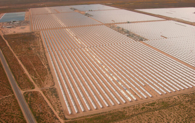
In spite of these drawbacks, power transmission by ropes might have a place in our energy systems. Today, there is a trend towards small-scale, decentralised power production, based on renewable energy sources. These solar panels, water turbines or wind turbines generate electricity, but whenever we need to produce mechanical energy, eliminating the step of generating electricity could result in a somewhat less practical, but more efficient use of energy.
A wire rope transmission powered by a water wheel in an open-air museum in Switzerland. Source: Historische Werkstätte Gebrüder Giger Mulin, Schnaus.
For instance, it is more efficient to power a circular saw by mechanical energy produced by a modern version of an old-fashioned windmill or waterwheel than to convert the mechanical energy generated by wind or water to electricity by a turbine, and then convert it back into mechanical energy for powering the sawing machine. If power transmission is required in such a scenario, a wire rope transmission would be the most efficient choice.
Long-distance Rope Drives
Another advantage of a wire rope transmission is that it can double as a transportation system, combined with an aerial ropeway for goods or passengers. As we have seen in the article on aerial ropeways, it was not unusual to tap power from a gravity-powered aerial ropeway to power a crane or other machinery. The combination of a wire rope power transmission with an aerial ropeway only works at lower speeds, so that power transmission capacity is limited. (An aerial ropeway was generally five times slower than a rope power transmission). Still, this could offer interesting advantages for small-scale power production, especially in mountainous areas.
It may be that the future of wire rope transmission lies in long distance power transmission after all, at least vertically. The only research field that dedicates itself to rope drive technology these days is that of high-altitude kite power. Kites could harvest large amounts of energy at high altitudes, where winds are stronger and steadier. Transmitting this energy to Earth is most advantageously done by mechanical power transmission, says researcher Dave Santos from KiteLab Group in an interview:
"Electric cables would be too heavy. With kites, power-to-mass-plus-aerodrag is critical, and the mechanical case wins by a large factor. Wire rope is not quite so amazing as our new materials, but good enough for a critical advantage over electrical. The main challenge is to learn how to drive ropes at speeds of hundreds-of-miles-an-hour."
Ultimately, the rope drive may turn out to be useful for the same reason it was originally designed: it could unlock the potential of awkwardly-situated sources of renewable energy.
Kris De Decker (edited by Deva Lee)
Sources:
- "Transmission of power by wire ropes", Albert W. Stahl, 1889.
- "A history of industrial power in the United States, 1780 – 1930. Vol 3: The transmission of power", Louis C. Hunter and Lynwood Bryant, 1991.
- "The wire rope and its applications", W.E. Hipkins, 1896
- "Description of a new method of transmitting power by means of wire ropes", W.A. Roebling, 1872.
- "Rope driving: a treatise on the transmission of power by means of fibrous ropes", John J. Flather, 1900.
- "Notice sur la transmission telodynamique / Short notice of the telodynamic transmission of motive power", C.F. Hirn, 1862
- "On the development and transmission of power from central stations", W.C. Unwin, 1894. (alternative link).
- "Der Constructeur. Ein Handbuch zum Gebrauch beim Mashinen-Entwerfen. Für Mashinen- und Bau-Ingenieure, Fabrikanten und technische Lehranstalten", F. Reuleaux, 1869
- "Drahtseil Transmission", Polytechnischen Journals (multiple articles, 1850-1910)
- "Drahtseil", Polytechnischen Journals (multiple articles, 1850-1910)
- "Transmission des Forces Motrices des Turbine sur le Rhône de la Compagnie Générale à Bellegarde", web page, retrieved February 2013.
- "La Télémécanique", web page, retrieved February 2013
- "Turbinenanlage und Seiltransmission der Wasserwerkgesellschaft in Schaffhausen", J.H. Kronauer, 1867.
- "A trade catalog on the transmission of power by wire rope", Carroll W. Pursell, Jr., Technology and Culture, Vol.16, No.1, January 1975, pp 70-73.
- "From shafts to wires", in "Journal of Economic History", Michael Devine, 1983.
- "Kritische Vergleichung der Elektrischen Kraftübertragung mit den gebräuchlichsten mechanischen Uebertragungssystemen", A. Beringer, 1883
- "Cours de mécanique appliquée aux machines", J. Boulvin, 1891.
Notes:
- Stahl, 1889
- The Stangenkunst at the Lady Isabella wheel was the most powerful installation ever built, transmitting 150 hp using wooden rods. For pictures, see part one of this series
- Flather, 1900
- Hunter, 1991
- Pneumatic and hydraulic transmission will be discussed in a forthcoming article
- Flather, 1900
- Hunter, 1991
- Beringer, 1886 and Unwin, 1894
- AC Transmission Line Losses, Stanford University, fall 2010
- More powerful motors are generally more efficient, less powerful motors are less efficient. The figures given are for a 100 hp motor, similar to the power transmitted at Oberursel
- Dave Santos, personal communication, February 2013